Bladed versions affected: all Bladed versions supporting model linearisation calculations.
Date of last article update: 14 September 2023
To check if this makes sense or not, the user is suggested to have a look at “$01” file provided in the simulation results (human readable if ASCII data is selected as the output). Here one will see a list of contributions from the uncoupled modes:
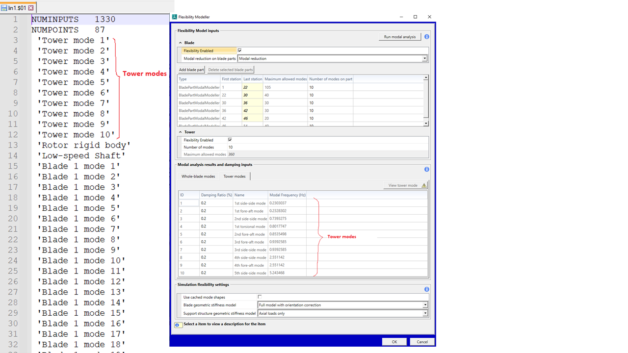
It can be depicted that there are 1330 uncoupled modes that are used to compute 87 coupled modes. As an example, the “Tower modes” labelled in above figure map directly with the uncoupled modes in the flexibility screen in Bladed User Interface (sorted by frequency) as shown in above figure, e.g.,
Tower mode 1 = 1st side-side mode
Tower mode 2 = 1st fore-aft mode
Etc.
Note that for blade uncoupled modes these can be more complex depending on the use of multi-blade coordinate transformation MBC (transformation to non-rotating frame) as:
Without MBC
displacement contributions to coupled modes from whole blade modes. But whole blade modes are different at each operating point.
With MBC
displacement contributions to coupled modes from rotor modes calculated in MBC.
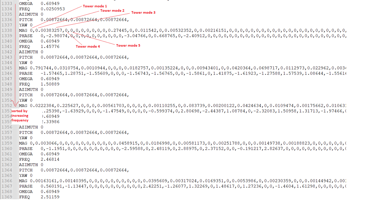
See below a screenshot of the “$01” file where the contributions of the uncoupled modes are listed. These are sorted by the frequency of the coupled modes (in vertical direction, see figure). The magnitudes of the contributions are indicated by the keyword “MAG” and are sorted according to the uncoupled modes listed on top of the “$01” file. Contributions below a specified tolerance will be set to zero. In version 4.15, the tolerance is set to 1e-6 and the values are presented in scientific notation, while in all previous versions, it is set to 1e-3 using standard notation. The change makes it easier to evaluate whether specific modes remain influential when dynamic stall or wake models are active.
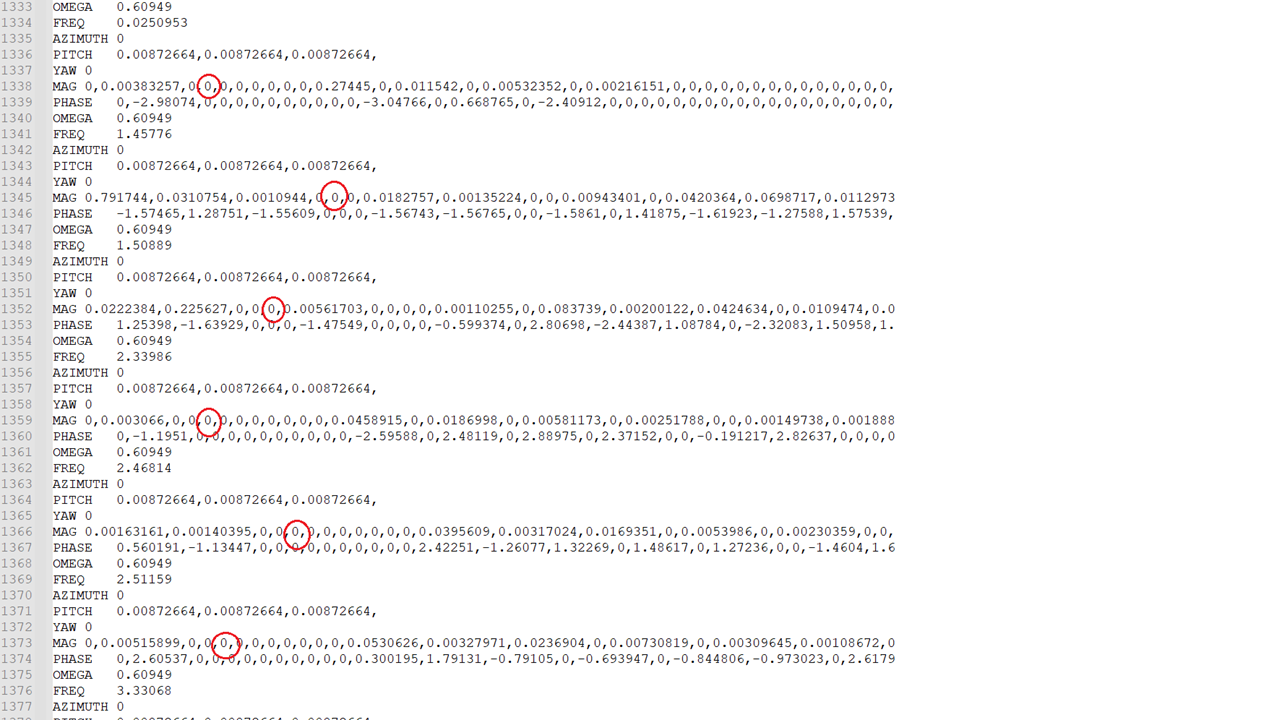
The fifth value of “MAG” corresponds directly with the “Tower mode 5” or 2nd fore-aft mode“ of the tower. It can be observed here that the value of this mode remains zero for all frequencies, which seems questionable (see below figure for more detail).
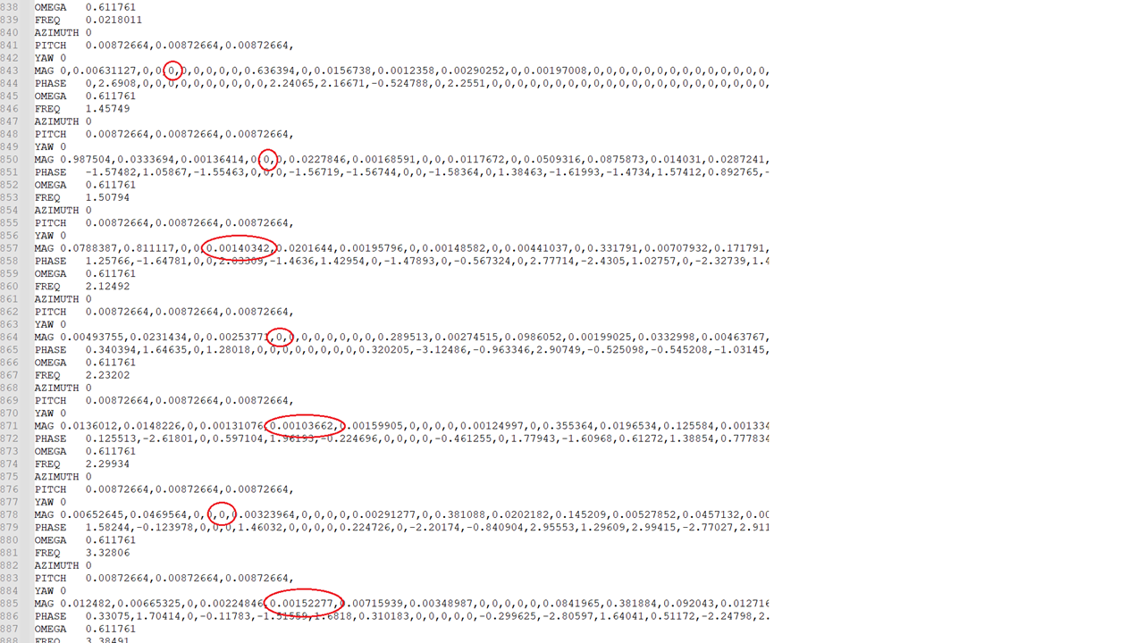
If the dynamic stall model is deactivated (as already recommended in practice for Campbell diagram), the contribution of the “2nd fore-aft mode” of the tower is now present for some frequency points, and is seemingly more correct.
The following two articles provide some other examples on how to interpret the results of the “$01” file and possibilities to plot the modes:
Plot coupled mode shapes from Campbell Diagram
Detailed guidance (with example) on how to plot coupled mode shapes