Versions of Bladed affected: All
Date article last updated: 28 June 2023
In the multi-member support structure model, direction cosines are used to specify the orientation of a support structure member. They can be quite confusing! An illustrative example should help understand these.
We imagine a unit vector in the direction of the member Z axis. These three numbers (the direction cosines) are the projected lengths of that vector along each of the three global (GL) axes respectively. (i.e. they are the components of the vector in the GL frame). So the sum of the squares of all three must always equate to 1.0.
For example. The member number 35 in the 5MW Tripod project (supplied with Bladed) is a vertical member. So its x axis is vertical, i.e. in line with the GL Z axis. If you look at the "Member axes" for this member, by default it looks like this: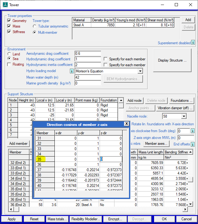
The cosine in the Y direction is 1, this means the angle between member Z axis and GL Y axis is zero, because cos 0 = 1.
The cosine in the X direction is 0, because the member Z axis is at 90 deg to the GL X axis and cos 90 = 0.
The cosine in the Z direction is also 0, because the member Z axis is at 90 deg to the GL Z axis and cos 90 = 0.
If you look at the 3-D rendering for this member, it looks like this:
But if you wanted this member's Z axis to be at, say, 60 degrees to the GL X axis, you would change the direction cosines to: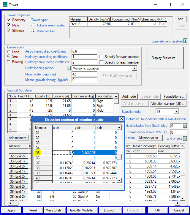
This then changes the orientation of the member Y and Z axes to look like this: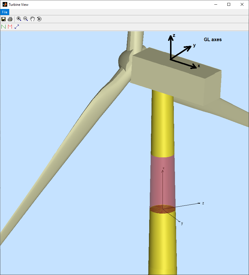
You will not be able to change the value in the "Z" cell because the member Z axis must always be at 90 degrees to the GL Z axis for a vertical member.
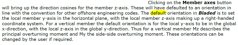
The default values chosen by Bladed are explained in the User Manual, i.e.: